Skip to Content

About: Tozato Measurements

Established in 2003, Tozato Measurements® is a worldwide technology solutions provider for steelmaking industry.

Recent Posts by Tozato Measurements

Frequency of the Oscillation Table: Cracks, bleeding, and breakouts can be associated with it?

Irregular frequency of the oscillation table generated by a failure in the liquid steel leveling sensor causes a great loss to production, quality, and maintenance.

Steelmakers observed that product downgrading in steel mills can be associated with problems with the oscillation table in continuous casting machines.

As reported by a customer, the maintenance team was dealing with excessive machine’s downtime.

Continuous breakout incidents or other problems related to the oscillation table and the mold, which in turn also concurred with decreasing in product’s quality, which came to show cracks and lapses regularly.

Discarted moulds showing damage caused by breakouts.
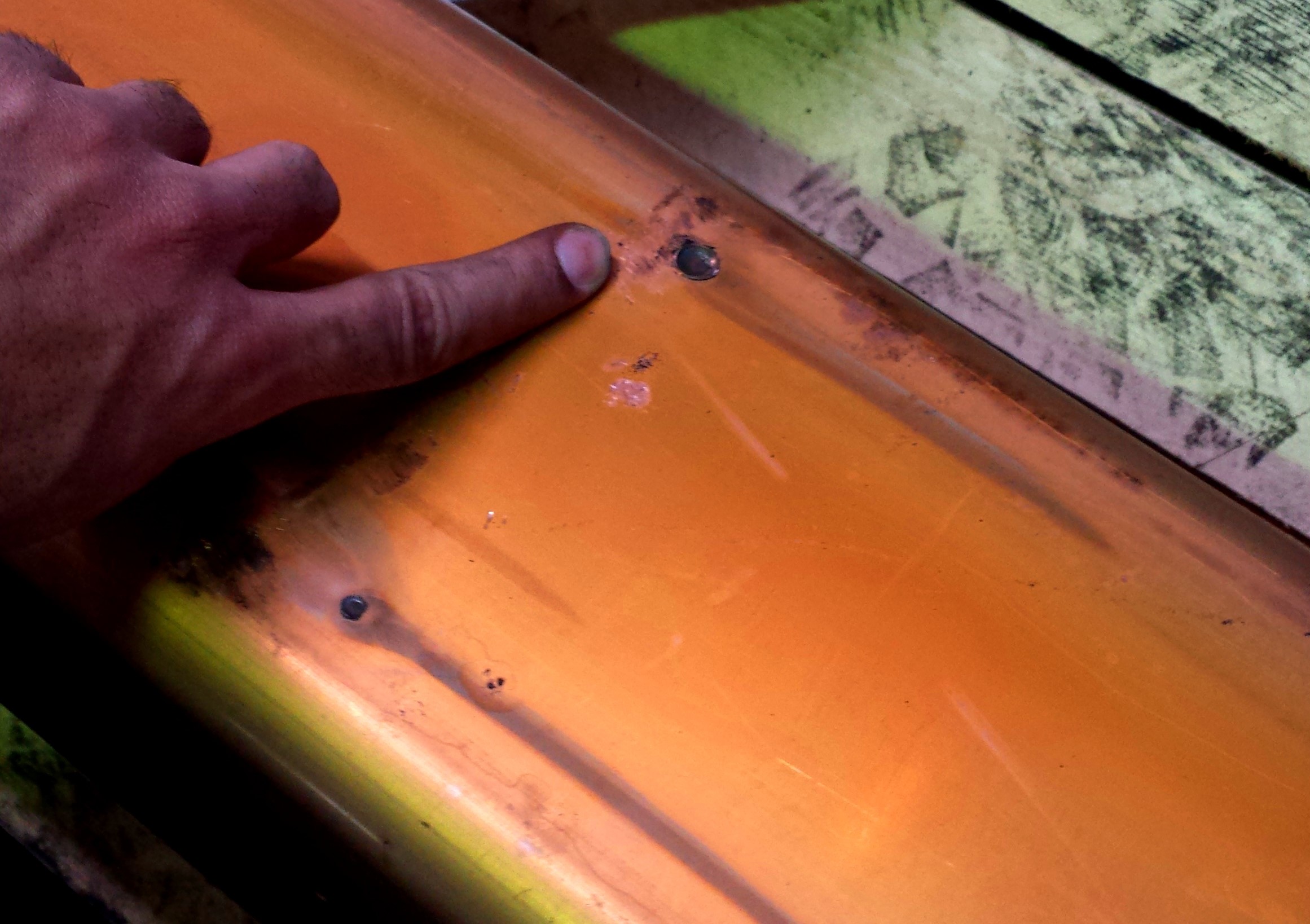
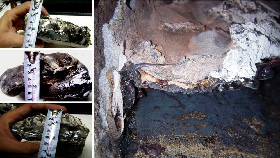
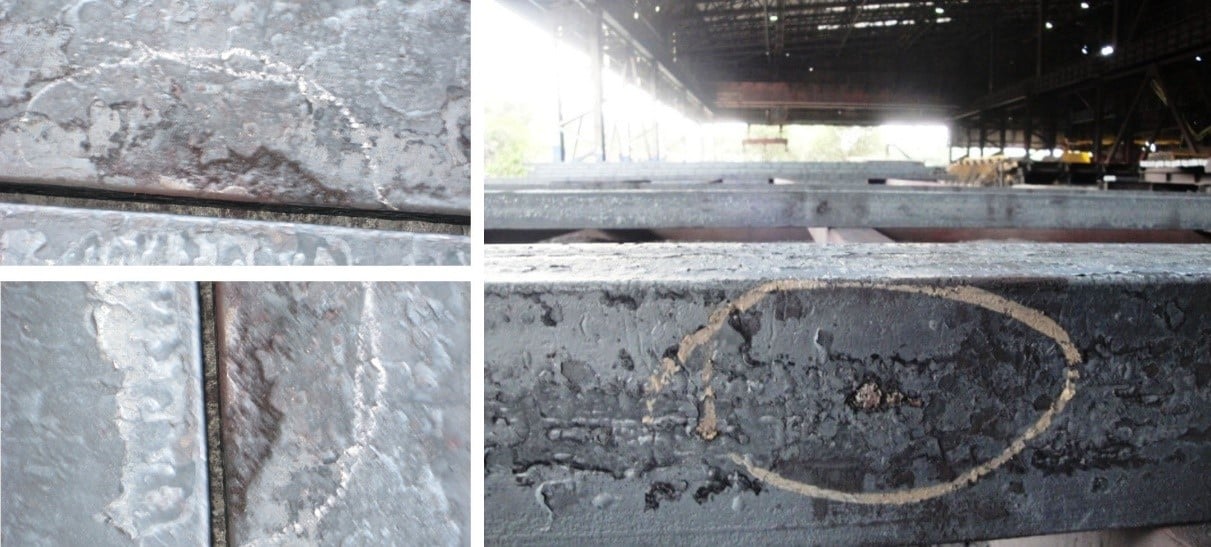
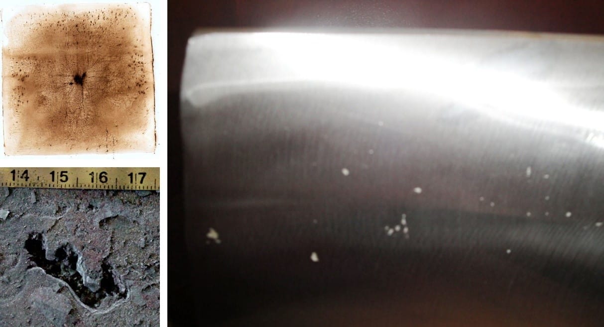
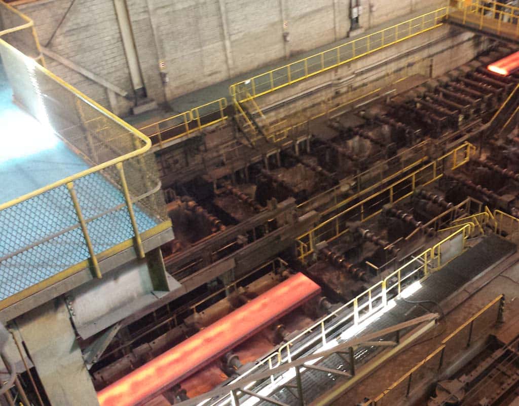
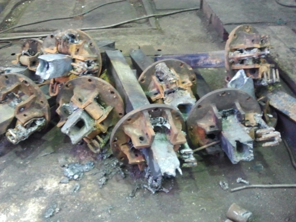
Picture 1: The picture shows the consequences of breakouts.

Discarted moulds showing damage caused by breakouts.
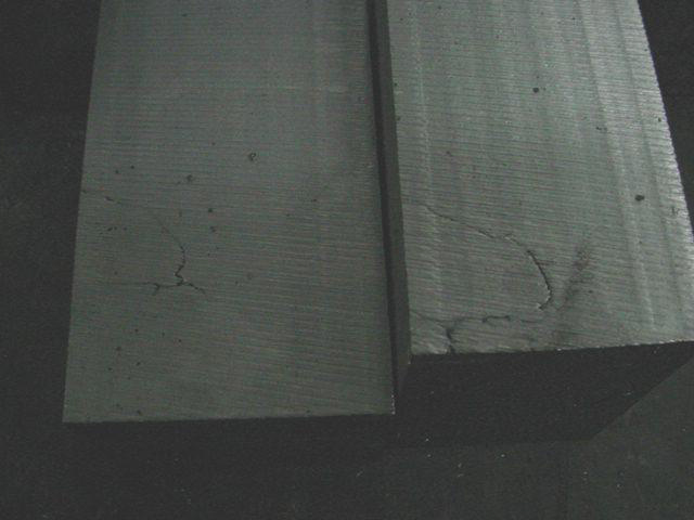
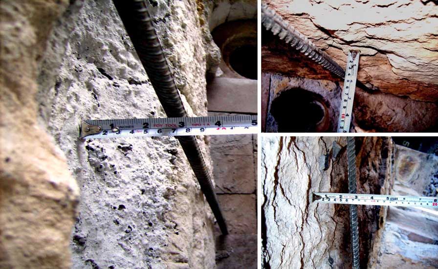
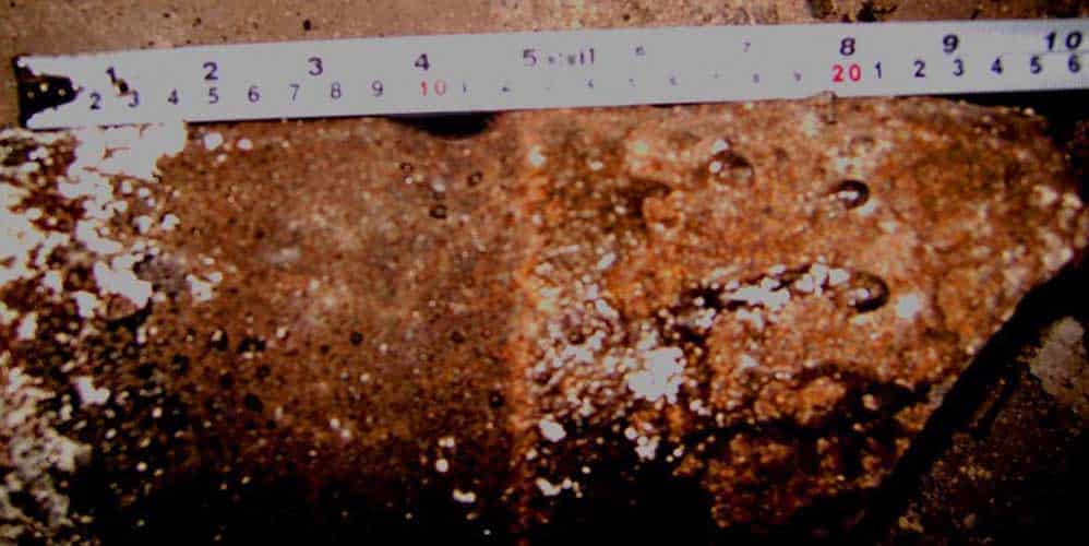
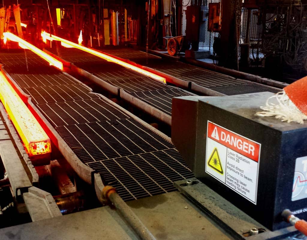
Picture 2: The picture shows cracks on both billet and bloom.

In order to investigate and solve the problems at the company, the customer contacted Tozato.

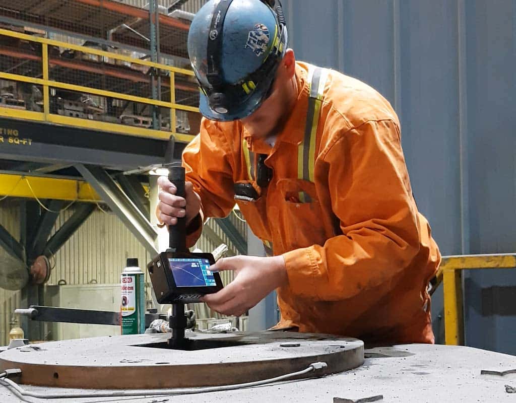
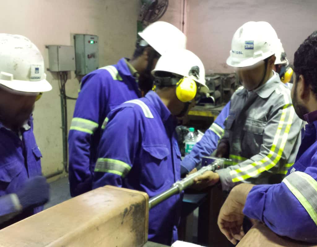
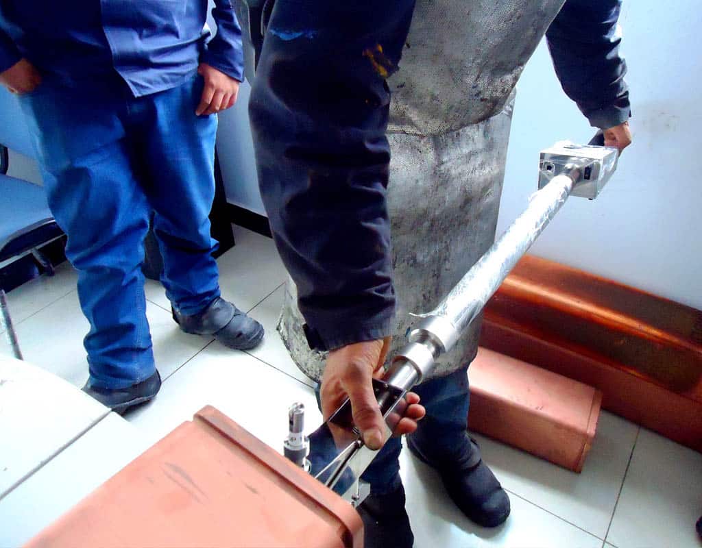
At the company’s request, Tozato’s engineering team traveled to the company to provide support and investigate the issue using a tri-axial sensor equipment, which analyzed the trajectory, vibration, and metallurgical conditions of the mold’s oscillator.

Frequency of the Oscillation Table’s problem detection and analysis

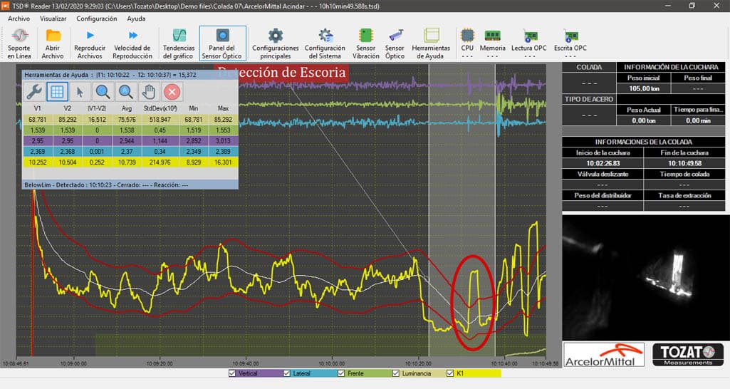
The problem was discovered after measuring the oscillation table with Tozato Measurements’ cutting-edge technology equipment. It was found that the oscillation table’s frequency was undergoing major changes (from 81 CPM to 116 CPM) in a matter of a few seconds.

This acceleration and abrupt reduction of frequency not only caused extra wear in the copper molds, but also resulted in constant breakouts in addition to causing product downgrading, forming severe cracks and recurring bleedings.

Discarted moulds showing damage caused by breakouts.
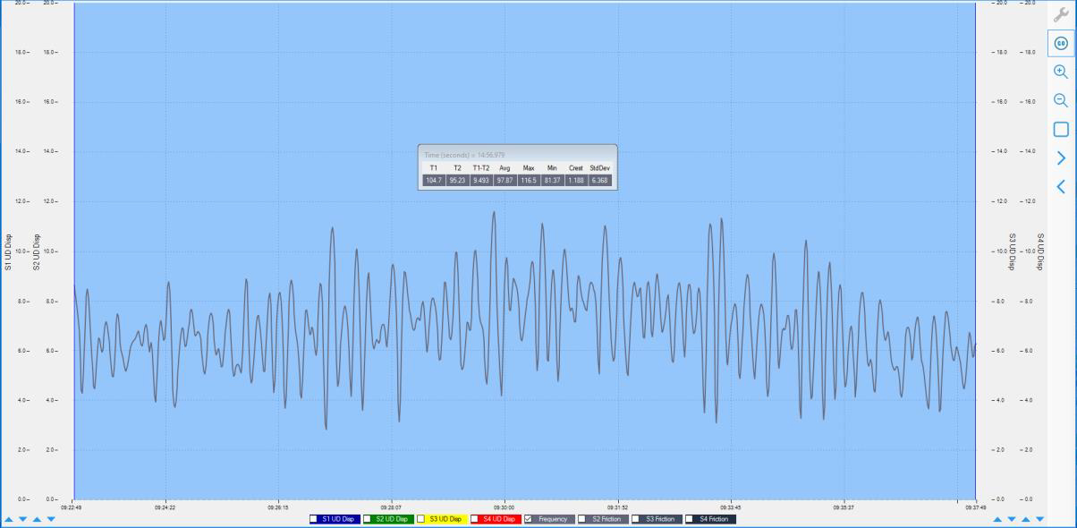
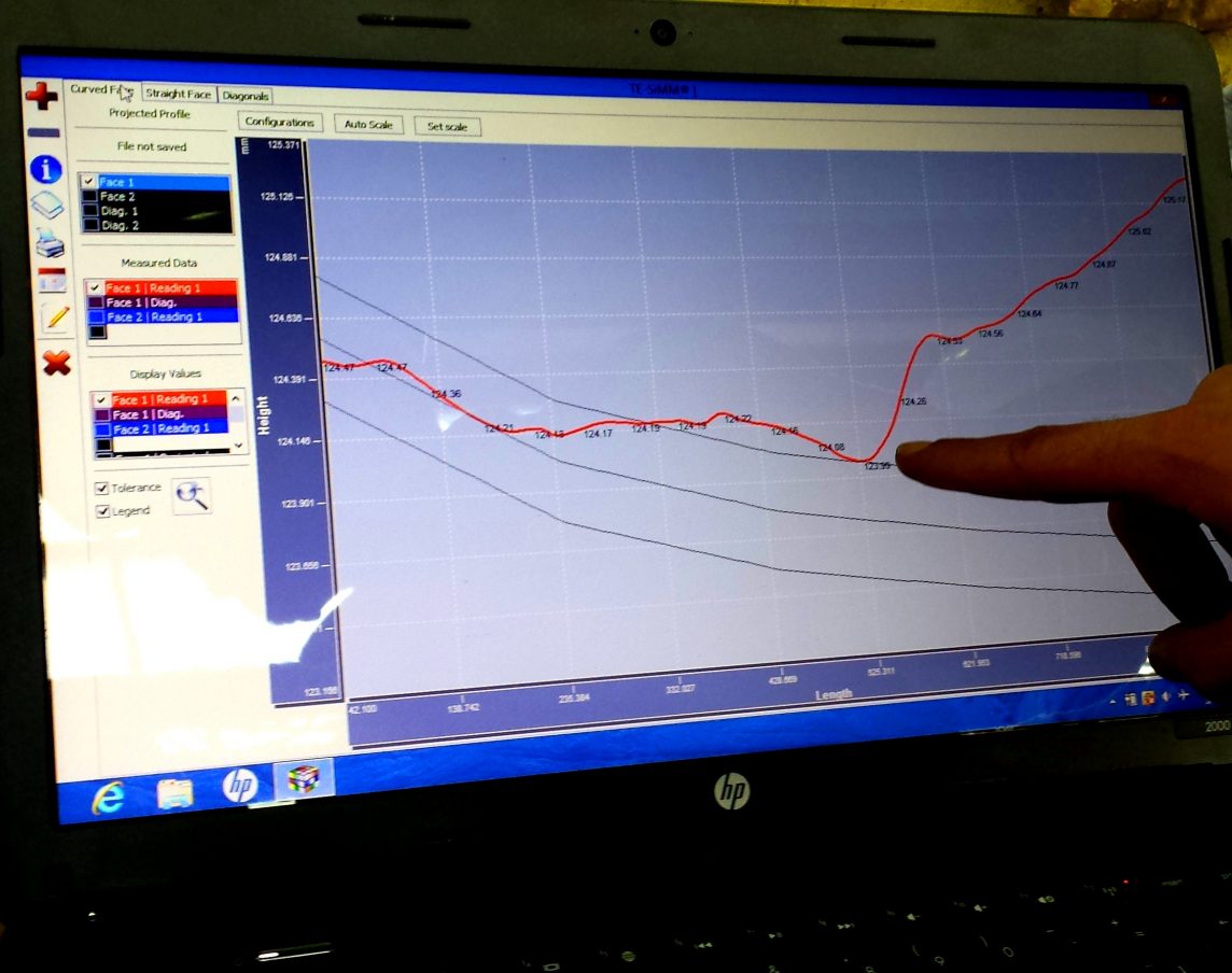
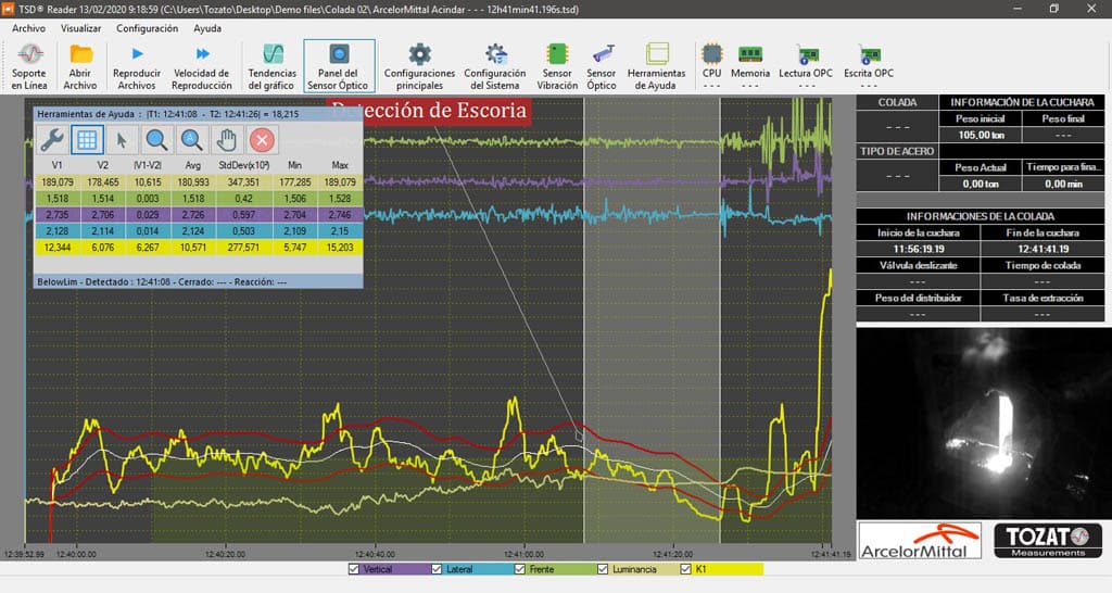
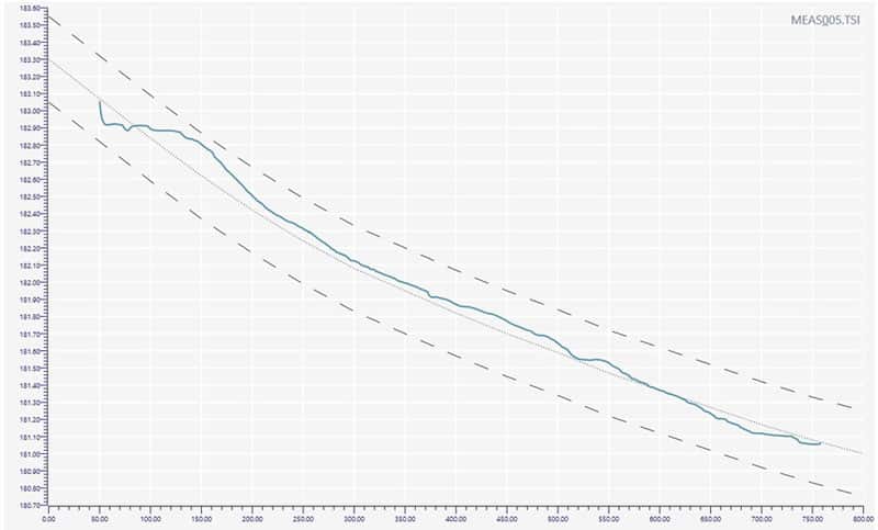
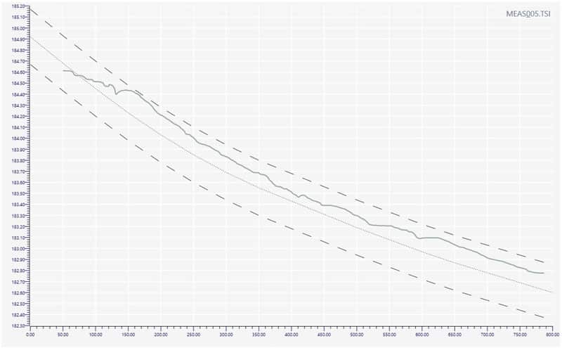
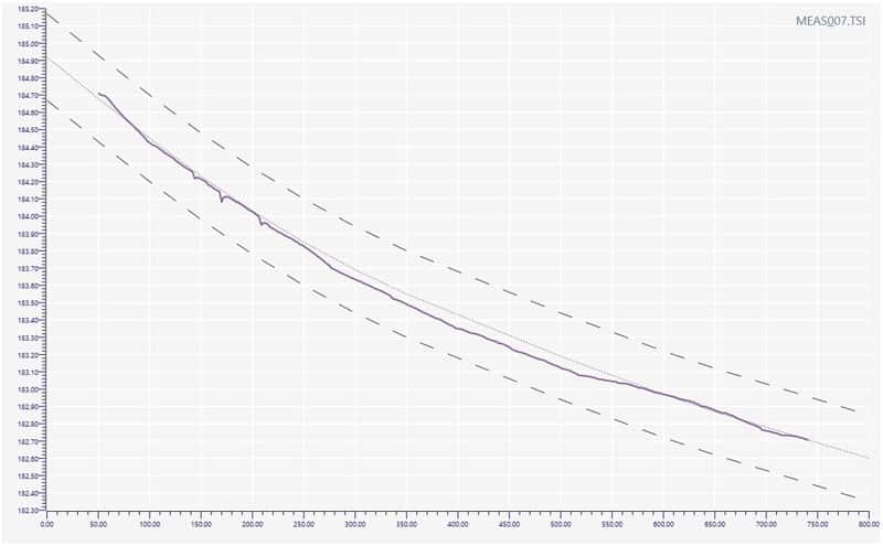
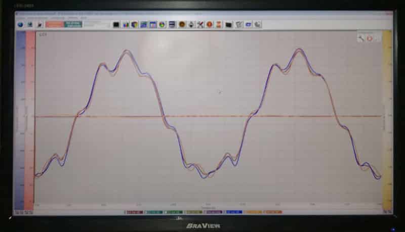
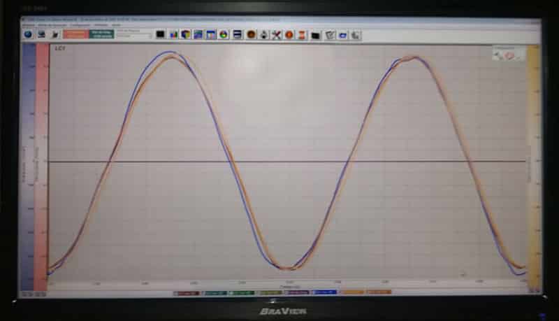
Picture 3: The picture shows irregular peaks of frequency of the oscillation table on the trend line.

The suspicion was that the high and rapid changes in the oscillator’s frequency were caused by the lack of calibration of the leveling sensor that assists in the distribution and volume of liquid steel within the copper mold.

Since it was without proper calibration, the motor was activated at the driver’s command to sometimes compensate the frequency, sometimes to reduce it.

Discarted moulds showing damage caused by breakouts.
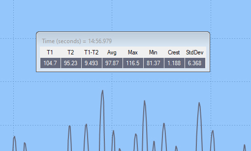
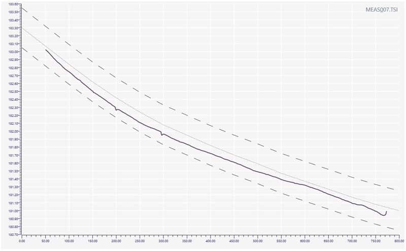
Picture 4: The picture shows, in the short period of exactly 14 minutes and 56 seconds, a variation of 81.37 CPM minimum and 116.5 CPM maximum.

It is common knowledge that the continuous casting machine operates from the motorized impulses which in turn assist the oscillation table and, at a steady frequency, provide high product quality. However, when there is a problem with the leveling sensor’s calibration, this frequency can change and cause major problems in the production and quality areas, as it was in this case with this customer.

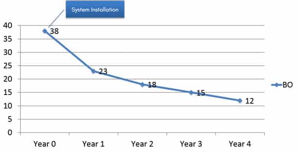
Immediate solutions were provided by Tozato’s engineering team. After identifying the problem and confirming the diagnosis using the monitoring system, the company requested the installment of Tozato’s continuous monitoring equipment to control the mold’s oscillation table.

Conclusion

As a consequence of Tozato’s high precision and resolution equipment, the company was able to increase the production, so that the quality of these products was within the required standards, avoiding greater expenditures with maintenance and product’s downgrading, since the use of this system increased the mold’s and the oscillation table’s service life, acting against rhomboidity and ovality, in addition to proving to be efficient in drastically reducing the incidence of breakouts.

0 0 Continue Reading →

Taper Loss: external deformation cause internal damage?

The link between deformation on the mold external surface and taper loss on its internal faces was unknown. The correlation between those two can only be noticed through a precise measuring equipment, which helps detecting internal anomalies, that happens to be millimetric.

The root cause for mold external surface deformity can be many, such as handling and transport errors and water jacket and screw assembling errors. Even though the copper mold presents a good mechanical resistance for its application, it can experience the consequences of those errors and present deformities. That way, when caused, those defects can lead to some several production problems, because once the taper is compromised, it is not possible to assure the proper steel skin formation.

[Case Study] Water Jacket Assembling Error

Recently a Tozato costumer identified an external surface deformity caused by a water jacket assembling error that ended up seriously damaging the taper on its interior. In this occasion, when proceeding with mold’s assembling in the jacket their screw got uncontrolled thigh up causing a warping on the external surface; As a consequence it constricted the interior face and caused taper loss.

Slag Detector Main Screen

In picture 1, the two areas that were most affected by extreme screw pressing are pointed. It is also perceptible that the warping is extended through the mold following the same direction.

It is worth mentioning that, to a naked eye, the warp caused by the jacket screws did not indicate to have caused a taper damage. Only by utilizing a measuring equipment, it was possible to detect this deformity, which at first would have go unnoticed. That said, the mold’s measurements showed the following results:

Slag Detector Main Screen

In the picture above, a severe warp is identified in the area indicated in the graph, which was most damaged by the assembling error. Besides that, from this point on there is wear that goes all the way to the mold end.

Production Risks

Using out of specifications molds can lead to defects on product’s surface, such as cracks (which have the wrong taper as one of their listed causes), besides the possibility of bleedings and breakouts. With measuring results in hands, it was possible to conclude that this mold was not inside the expected profile; thereafter it could represent a risk to the production if not discarded.

Slag Detector Main Screen

For example, product downgrading is one of the damage provoked by a breakout, as we can see in Picture 3: a thin steel skin that has ruptured during negative strip process due to ferrostatic pressure.

Conclusion

That said, it becomes evident the necessity to create a preventive maintenance culture, that utilizes precise technology like the ones provided by Tozato, aiming to avoid new and old molds improper use, considering the many disadvantage that can occur from the sum of this situation. The preventive maintenance will help to increase the mold’s service life, reduce the product defects, like cracks and breakouts, reduce machine downtime, as well as avoid the premature discard of the mold.

0 0 Continue Reading →

Slag carryover from the ladle to the tundish: why control?

The improper slag carryover from the steel ladle to the tundish promotes the accumulation of this material in the tundish, as well as causing corrosion and greater wear of the refractory. To avoid further damage, the number of heats per sequence is limited. Hence, due to the decrease in the number of heats, the remaining steel inside the tundish represents a reduction in metallic yield, and conversely, increase the cost of production. In addition, when slag reaches the final product, it accumulates in inclusions that directly affect product quality.

Therefore, to achieve positive results during the process, slag carryover control is necessary, and in this study, the slag detection system proved to be a tool capable of reducing the timing of slag carryover from the ladle the tundish in 8.6 seconds, when compared to the traditional detection method.

Slag detection: traditional method x detection system

Aiming to increase the metallic yield and the final product quality, a Tozato customer hired the slag detection service.

In one of the tests performed, an interval of 15.3 seconds was verified between the moment when the system detects the slag carryover and the moment when the operator manually closes the slide gate as it can be seen in Picture 1.

Slag Detector Main Screen

Picture 1: Moment of slag detection by the system (15.3 seconds before the flow is stopped).

The red circle in Picture 1 highlights the moment when the ferrostatic pressure in the ladle decreases. The operator, unaware of the start of the slag carryover, instead of closing the gate, opens it further, pouring more slag into the tundish and thus increasing the layers deposited in the container.

In another case, the time between the detection of the slag carryover through the system and the closing of the slide gate was even longer. The slag / steel flow until the gate shut down was 18.6 seconds as can be seen in Picture 2.

Slag Detector Main Screen

Picture 2: Moment the system detects slag (18.6 seconds before the flow is stopped).

In this second case, there is an increase in the slag pouring time in relation to the first, which indicates that without a precision tool, the operator is subject to a great variation in the reaction time for closing the gate.

Thus, based on the slag detection system used in this study, Table 1 created with the records of the operator’s reaction times for closing the ladle, and the referred amount of slag and steel poured into the tundish in tons, at an average extraction rate of 105 ton/h.

Record

Reaction Time (seconds)

Extraction Rate (ton/h)

Slag + Steel (ton)

1

15.60

105

0.455

2

1.80

105

0.053

3

18.60

105

0.543

4

8.10

105

0.236

5

4.30

105

0.125

6

3.60

105

0.105

Average

8.60

105

0.250

From the data presented in Table 1, it is possible to conclude that the average reaction time of the operator, after the detection of the slag by the system is 8.6 seconds. Therefore, considering the average extraction rate of 105 ton / h, it is estimated that a surplus of approximately 250 kg of slag and steel will be poured from the ladle to the tundish per heat.

Benefits of the slag carryover control

It is worth mentioning that the increase in metallic yield and product quality are the main benefits sought by this customer with the use of the slag detection system. It is important to note that it is necessary to have a balance between yield and quality in order to assess the amount of slag that is acceptable in the tundish. In addition, the following benefits are observed:

  • Operational Benefits
  • Increased Metallic Yield
  • Increased Tundish Service Life
  • Increased Shroud Service Life
  • Greater Safety for Operators
  • Increased Product Surface and Internal Quality

Operational Benefits

The accumulation of slag in the tundish requires undesired process outages to slag off and prevent it from reaching the final product. Then, the detection of the slag carry over by a precision tool reduces the number of stops to slag off the tundish. Operationally, more heats can be done in a sequence.

A great benefit for this client, since there was a deposit of 10 mm of slag per heat (Figure 3).

Slag Detector Main Screen

Picture 3: Typical accumulation of slag in the tundish that reaches 10 mm per heat.

Increased Metallic Yield

This customer closed the gate to prevent slag carryover when the ladle reached a certain average weight. The gate was often closed early. With the use of the slag detection system, it was possible to reduce the remaining steel, achieving savings of up to 1.2 tonnes per ladle, resulting in a substantial increase in metallic yield.

Increased Tundish Service Life

The reduction of slag poured in the tundish proportionally reduces the chemical and physical processes, corrosion and wear of the refractory and the components used to drain the tundish, as shown in Picture 4. Therefore, there is a possibility to increase the tundish service life.

Result of refractory corrosion and wear due to the accumulation of slag.

Picture 4: Result of refractory corrosion and wear due to the accumulation of slag.

Increased Shroud Service Life

The accumulation of slag in the tundish causes wear on the shroud as the submerged part maintains constant contact with the metallic bath, which is possible to see in Picture 6. Therefore, the smaller accumulation of slag in the tundish causes less corrosion and, therefore, increases its service life.

Example shroud wear due to slag accumulation

Picture 5: Example shroud wear due to slag accumulation.

Greater Safety for Operators

Tundish breakouts, caused by the deposit of slag, represent a great danger for operators. However, when the amount of slag poured is less, the chance of corrosion perforations that may occur in the tundish is also reduced.

Increased Product Surface and Internal Quality

The greater the amount of slag remaining in the tundish, the greater the chances of the slag reaching the final product of the casting and agglomerating into inclusions, as it can be seen in Picture 6 and Picture 7. Its presence negatively affects the mechanical properties of the product, which can lead to the formation of cracks and downgrading. Therefore, the absence of slag represents a higher surface and internal quality of the product.

Surface and internal defects caused by slag inclusion in the final product.

Picture 6: Surface and internal defects caused by slag inclusion in the final product.


Picture 7: Surface and internal defects caused by slag inclusion.

Conclusion

This paper points out that with the use of the slag detection system it is possible to reduce on average 8.6 seconds of material flow poured into the tundish, which corresponds to approximately 250 kg of slag and steel and to have a gain in the metallic yield in 1.2 tons per heat.

In addition, with the reduction of the slag carryover, the accumulation that used to reach 10 mm of slag per heat will decrease proportionally. Therefore, in long term, it will be possible to observe the increase of tundish refractory service life, which will no longer potentially suffer the chemical attack by the oxides present in the slag. From an operational point of view, the number of heats per sequence will be greater, as the process will not need to stop to empty the slag boxes.

Finally, it is possible to conclude that there is no advantage in allowing the slag carryover from the ladle to the tundish, and the acquisition of a system capable of detecting the slag carryover in this step of pouring the liquid steel is a fundamental tool when it is desired to achieve higher quality and performance.

0 0 Continue Reading →

Cracks due to copper mould meniscus deformation

Recently, a customer hired Tozato Measurements reporting cracks in their product in a particular strand. The cause was unknown, so the work was to investigate the possible problems that would lead to cracks formation.

The procedure consisted in analyzing the internal condition of a 180 mm x 180 mm copper mould which was being used, and checking its conformity to the desired taper and profile.

Measurements and Data Gathering

A mould profilometer system was used to check a 180 mm squared mould profile with a service lifetime of only 50 heats. The readings were performed for both straight and curved face.

Firstly, the data was collected for the straight face and Figure 1 shows a screen from the equipment software which abnormal and deformation is visible in the meniscus region.

Measured graph with deformation at meniscus area

Deformation found in the meniscus area for the straight face.

Secondly, the data was collected for the curved face of the mould, which also presented notorious deformation in the meniscus area. The software screen showing the deformation in the region can be seen in Figure 2.

Measured graph of a curved face with deformation at meniscus area

Deformation found in the meniscus area for the curved face.

Thus, both straight and curved faces of the mould presented accentuated deformation in the meniscus, which can easily explain the cracks on the product. However, some more investigation was needed.

Further Investigation of Cracks Causes

Once found noticeable deformation in the meniscus area of a copper mould with only 50 heats, a concern was raised towards the mould condition previous to the casting moment. Was the mould already worn when first put in operation or was the mechanical conditions of the oscillator that caused the deformation?

Thereby, measurements were done in an identical brand new 180 mm x 180 mm copper mould, with no heats performed, which allowed to collect the data presented in Figure 3 and Figure 4.

Measured graph with no deformation

No deformation found in the straight face of the brand new mould.

Measured graph with no deformation curved face

No deformation found in the curved face of the brand new mould.

Once identified that the straight and curved faces did not present deformation in the meniscus for the brand new mould, the customer started investigating the possible causes for the deformation in the particular region, following the orientations of which would be the most appropriated tool for this purpose.

Upshot

Meniscus deformation is considered a critical abnormality which leads to serious problems in the product quality. The company needs proper tools in order to be able to prevent issues such as prematurely worn moulds or undesired taper for the specific steel grade. Thus, only with the possession of appropriated technologies, it was and it is possible for the customer to identify the real cause of the problem.

0 1 Continue Reading →

Production errors anticipating through monitoring

How many production errors and issues could be avoided through constant monitoring of oscillators?

Many accidents signalize their occurrence long before they happen and, most importantly, it is possible to prevent if you have the right tools at your disposal. Thus, the monitoring of mould oscillation is a determining factor for accident prevention and production errors that can cause damages and losses to the process.

Aware of that, a customer of Tozato Measurements installed an online system for monitoring the oscillation of the mould, looking to have total control of its process and anticipate errors that could cause losses and many headaches.

A right decision made.

Preventing production errors

With the installation of equipment capable of permanently monitoring the condition of oscillators, operators have at their disposal a wide variety of fundamental information. Through the use of high precision and speed tri-axial accelerometer sensors, data collection is able to monitor the trajectory, vibration and metallurgical parameters of the continuous casting process.

Using the TOM data, the customer found that the oscillator’s vertical velocity waveform began to show an irregular pattern, which indicated that the continuous casting machine was not operating in its full state of efficiency.

Oscillation curve with an irregular pattern, indicating production errors.

After finding the cause of the problem, the machine’s eccentrics were changed and the waveform immediately returned to a clear sinusoidal pattern.

Oscillation curve with a regular pattern, indicating a CCM free of production errors.

“Had the problem not been anticipated, it would have been much worse. This maintenance, pointed out by the system, helped us to avoid an unexpected outage of more than 10 hours. So, we managed to keep the schedule and avoid a lot of headaches and annoyances”.

Breakout prevention

Evidently, that was not the first time that the relationship between the monitoring of oscillation and the reduction of accidents and production errors could be seen.

Another time, other customer had already pointed out the installation of the mould monitoring system as a determining factor for the reduction of almost 70% in the annual incidence of breakouts.

CCM Break-Out down rate over the years

Online monitoring benefits

The mould oscillation monitoring systems are applied to monitor the real time conditions of the mould oscillators of continuous casting machines in order to verify vibration, trajectory and metallurgical parameters of the steel casting process.

Mould oscillation monitoring is carried out aiming to achieving the following purposes:

  • Evaluate the mechanical conditions of the oscillator;
  • Monitor the steel continuous casting process;
  • Monitor the characteristics that influence the product surface quality;
  • Create a history of oscillator wear trends;
  • Reduce preventive maintenance downtime;
  • Optimize time and resources;
  • Increase the service life of oscillators and copper moulds.

UPSHOT

Unquestionable results such as this can be achieved thanks to the intelligent application of resources. Through consistent application of oscillation monitoring, it is possible to achieve results that benefit both the production and maintenance sectors.

Therefore, more and more steelmakers around the world are engaging in control to achieve their goals.

0 0 Continue Reading →

Friction and its Relation with Internal Mold Condition

There is a relation between the mold internal condition and the oscillation friction during the continuous casting process. This relation, however, was only proved after applying both Mold Oscillation Monitoring and Mold Profile Checker simultaneously. Check out the results down below.

0 1 Continue Reading →

Metallic yield loss and cutting control through contact methods

Metallic yield loss associated to contact cutting control methods may accumulate great losses over time. Why those methods based on limit switches and encoders cannot reach cut-to-length consistency and accuracy for billets, bloom, beam blanks, and slabs? Moreover, why is this length variation mostly higher than 2 in (50 mm)?

4 2 Continue Reading →

Surface and format defects caused by using wrong mold profile

Surface and format defects as well as breakouts may be caused by wrong mold profile and /or irregularities in the cooper mold profile. Knowing these failures is the very first step to prevent to become the next victim and accumulate losses. When it comes to such important part of steel making process, which is the CCM copper mold, some care and regular maintenance practices are of utmost importance to ensure its proper use.

1 0 Continue Reading →

Can brand-new copper molds present profile mismatch?

Purchasing new molds for continuous casting machines is a daily basis procedure in the steel plant environment. In most instance, confident on the information provided by the manufacturer, brand-new copper molds without passing through any internal and dimensional taper overhauling process replace outworn ones. However, Tozato technical team performed case studies that testifies the need of checking the mold profile, even in brand-new copper molds.

2 0 Continue Reading →

LVDT and its readings on hydraulic continuous casting machines

A usual mistake made by companies that work with hydraulic continuous casting is to assume that the LVDT (linear voltage displacement transducer) is able to provide reliable information regarding the oscillation performance. However, the LVDT does not provide any kind of information directly on the oscillation table itself. It only is capable to give information about the hydraulic cylinder performance

1 2 Continue Reading →


Recent Comments by Tozato Measurements